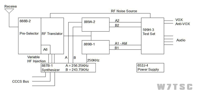
599H-3 - Test Set
Routes audio from IF Translators to Local Control, provides RF Noise Source, VOX and Anti-VOX circuits
The difference between the low level and high level self-test is that high level self-test has one more amplifier applied.
652J-4 - Power Supply
Provides all switched and continuous voltages to all other GRR-18 Slices
The continuous voltage oscillator section is enabled by 120VAC applied when that circuit breaker is placed in ON position.
The switched voltage oscillator section is enabled by a ground through the 1A31A6 Air Flow Interlock
47-460Hz is the frequency of the two oscillator sections (400Hz secondary oscillator output with 115VAC)
115VAC at 400Hz is NOT monitored by A1U1
887B-1 - Frequency Synthesizer (Same as Exciter)
Produces all frequencies necessary for mixing:
- 9.9MHz
- 9.9KHz
- 250KHz
- 256.25KHz
- 243.75KHz
- Variable injection
9.9KHz Phase-Lock-Loop (ØLL) outputs 107.1500 - 79.1501MHz to RF Translator
10KHz ØLL outputs 93.29 - 64.31MHz to 9.9KHz ØLL
9.9MHz ØLL provides outputs of 9.9MHz to 9.9KHz ØLL, A20 x10 multiplier, 6.29KHz multiplex divider, and a 100KHz reference to the 250KHz ØLL
250KHz ØLL provides 250KHz reference to 6.29KHz multiplex ØLL and 250KHz to 889B-1 for demodulation
6.29KHz multiplex ØLL provides 243.710KHz and 256.29KHz to the 889A-2 for demodulation
888B-2 - RF Translator
Preselector and RF translator - converts RF to IF
Preselector rejects all signals +/- 10% of desired
Converts RF to 250KHz IF
Preselector is normally energized in RCV mode, but will DE-energize if logic-level 1 comes in from RCV Overload Monitor A3 P1 Pin 38 or Frequency Change 7msec logic-level 0 or if radio is in self-test
A20K4 enables bandswitching motor, A20K5 energizes for self-test to bring RF Noise Source
Tuning process is started by a 70msec change pulse sent to the tune logic card A3. The A3 takes the BCD information from the DCFE and instructs the bandwitch S6, and S1A (in the preselector) to turne the capacitor C1 to the proper band.
889A-2 - A2/B2 Sidebands
Converts IF to Audio for the A2/B2 sidebands
Uses 256.29Khz for A2
Uses 243.71KHz for B2
889B-1 - A1/B1 Sidebands
Converts IF to Audio for the A1/B1 sidebands
250KHz injection for both A1/B1
The primary difference between the two cards are the sideband Filters and Injection Frequencies
Notes:
- Exciter slices 887B-1 and 652J-4 can be interchanged with the same Receiver slices.
- Main Breaker applies power to the rack
- RCV Breaker applies power to the 652J-4 to turn on continuous voltages (Blower Breaker must also be ON)
- Enable Receiver at OK-145 Control head
- When positive air pressure is felt (from the blower) interlock 1A31A6 closes providing ground to Control switched voltages in the 652J-4.
- Voltages are then routed to individual areas
System will NOT Tune Complete until the PA does.