Converting an AN/TSC-60(V)9
from 3-phase to Single-phase power
This article also available as a PDF from the Download Area.
The AN/TSC-60(V)9 is a military-procured HF communications facility housing two Rockwell-Collins HF-80 radio systems. Like many other military mobile electronics facilities, it’s powered by 208VAC, 3-phase, typically from a generator source. This is fine for a collector as long as 3-phase is available from the power company, a rotary phase converter and appropriate transformer is at hand, or a 30KW 3-phase generator happens to be lying around. Each option comes with its own costs and challenges to get operational. This paper outlines the effort and success of converting my (V)9 to use common 240VAC single-phase power within the goal of making all changes reversible back to the original design.
To be fair, I have access to a military surplus MEP-005 generator that is capable of supplying 3-phase power to the van (I call the facility a “van” from way back in my National Guard days). However, the generator does not run consistently despite my best efforts to repair it. Therefore, at some point it becomes a costing exercise. The question is “what’s cheaper?”
- Repair the generator further – time, effort, more money
- Have the utility provide 3-phase power to my property – very expensive
- Buy a rotary phase converter and transformer – costs about the same as replacing the MEP-005
- Run 240VAC single-phase and convert the van – zero dollars inside the van (a couple hundred to get power to where the van was)
I also had to answer the question “am I okay with not being able to run the facility if grid-power goes out?” The answer to that was “yes,” because if it came down to it, I could still power what was minimally needed for emergency communications by using a small 5,000 Watt single-phase gas generator. The last question needing answered had to do with how much of the actual equipment inside the van used 3-phase power.
When I took possession of this van, I was lucky enough to also get manuals that showed the power entry, power distribution and wiring of the facility. This enabled me to trace power from where it came into the van, to where it eventually ended up at each piece of equipment. It soon became apparent everything in the van used just one of the three legs of the incoming 3-phase for about 110VAC, except the Environmental Control Unit (ECU) and Power Amplifiers (PAs) which used all three legs of the 3-phase.
The HF-8014A Transmitter and HF-8054A Receiver radios each use 110; one set of radios on each of two legs from a main breaker. All the console equipment uses 110, the lights, outlets, etc. all use 110. My research then turned to the question of whether or not the PAs and ECU could be converted from 3-phase to single-phase. I attacked the question of the ECU first.
The ECU technical manual TM5-4120-384-14 covered the wiring diagrams and information outlining the differences between the 3-phase and single-phase models. TM5-4120-384-24P covered the parts. Converting a 3-phase model to single-phase would be a daunting task requiring the addition of large capacitors and relays, and extensive re-wiring. I decided it would be much better to try and source a single-phase model or replace with a conventional and modern 240V single-phase in-wall unit. I felt this could be accomplished with no modification to the facility other than building a frame to house the replacement ECU on the same rack the original unit lived. The ECU conversion will be covered separately.
Once the decision on the ECU was made, that left the question of the Power Amplifiers; therefore, I queried the Collins Collectors Association and was given information on how easy it would be to convert the PAs. The PA could be strapped for any number of different voltages, either single or 3-phase. This was a matter of providing the necessary voltage to the proper pins and move a jumper inside the cable plug to the proper set of pins. Overall, the job should be easy.
It soon became clear in my case, the least painful resolution was converting the van to 240 single-phase. I already had a 240VAC 200 amp service nearby, electrician friends and my research on the conversion proved converting the van would be fairly simple. To start, I ran a 100 Amp Service Disconnect to a post near the facility. This effort is where the only real cost came in to play; a few hundred dollars for running a new ditch, the conduit, wire, breaker, box and fuses. Then it was a matter of analyzing the details behind the conversion in the van and making as few changes as possible, again making sure everything was easily revisable.
Incoming Power
NOTE: All changes to power wiring were done with incoming grid-service POWER OFF both at the main breaker for the service and at the Service Disconnect.
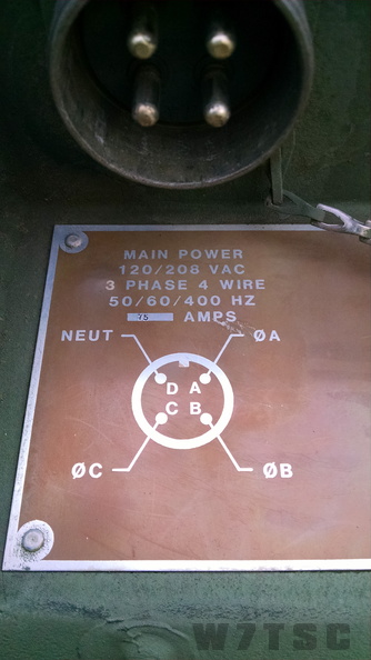 |
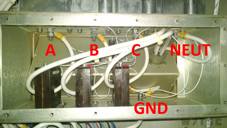
Power to the facility is provided through a four-conductor cable and separate ground. A ground rod is driven at the van and cabled to a ground lug on the van and also to the generator. The pinout is labeled on the outside of the Van. Internally, the three “hot” wires first go through current sensing loops (to monitor amps on a meter) and then to RFI filters before routing to the Main circuit breaker. Neutral is wired directly to an RFI filter and ground goes directly to a ground lug.
|
The goal was to make as few changes as possible here. The power cable had a connector on one end that attached to the van, the other end was bare wire attached to lugs on the generator. All I needed to do was move the cable from the generator to the service disconnect and hook up the appropriate legs. I began by “toning” the cable with a multimeter to find out which color was on which letter of the connector. I then determined which color wire should be connected to which power leg of the service disconnect. I also decided to run ground via the cable since I only needed two hots, and one neutral; that left one wire in the cable unused which I used for ground instead.
Here is the wiring scheme used to supply 240V single-phase to the shelter:
| Cable Letter | Wire Color | At Service Disconnect | Inside Van |
| A | Red | Hot 1 | No Change - Goes to Phase A - BUS A via Main Breaker |
| B | White | Hot 2 | No Change - Goes to Phase B - BUS B via Main Breaker |
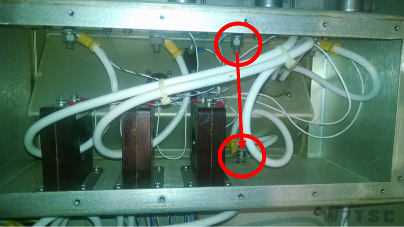
| C | Black | Ground | Incoming Wire removed from FL3, taken out of sense loop, and attached to Ground. This became ground from the service disconnect |
| D | Green | Neutral | No Change |
This scheme required only one change inside the power entry panel. This left no connection at all through the third hot leg “sensing loop” or RFI filter. This would leave no power connected to the third leg of the main breaker inside the facility. Note how the “C” incoming wire has been removed from the third (from left) RFI filter, unthreaded from the current sensing loop, and attached to the ground lug. Neutral stays where it is.
Power Distribution
With the changes to incoming power done, I closed up the Power Entry panel and moved on to Power Distribution.
NOTE: All changes to power wiring were done with incoming grid-service POWER OFF both at the main breaker for the service and at the Service Disconnect.
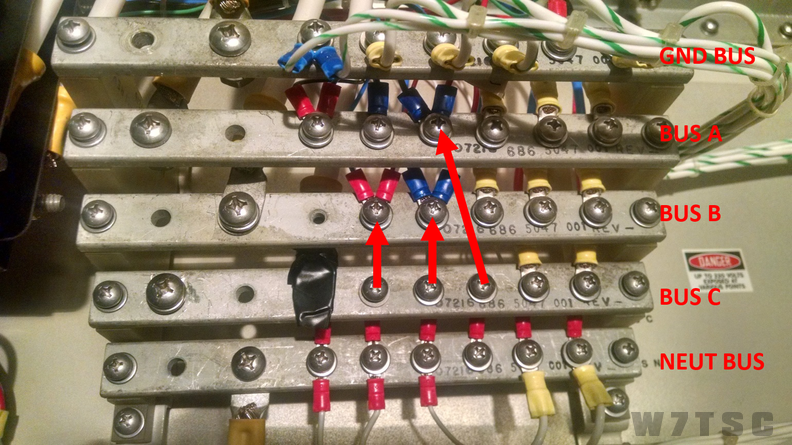
After the Main breaker, the three legs of power and the neutral are wired directly to a power distribution bus. From there, power is wired to each of the breakers for Power Amplifiers, Receiver/Exciters, ECU, and to two terminal strips (TB2 and TB3). The power bus is stacked with Ground on top, then Bus A, B, C and Neutral on the bottom.
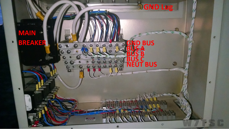
The objective was to move all the BUS C items to either BUS A or BUS B. Before starting, I needed to find out what each wire went to, understand the load and distribute them evenly between BUS A and BUS B. The incoming feed to BUS C came from the Main breaker to what we’ll call hole number one. This is the first available connection on the strip after the mounting screw on the left. There are eight available mounting holes on the BUS.
Figure 4 shows a total of five connections from BUS C, not counting the incoming power wire. Two wires were heavier gauge than the remaining three, indicating a higher power load. Investigation revealed the largest two wires were the C-phase for the PAs and the ECU. Being I didn’t need to use the third phase for any of that equipment, I was able to simply leave them in place on the BUS C bar with no need to remove them. The remaining three smaller gauge wires went to a 3A circuit for the shelter blowers, a 5A to Antenna Coupler 1, and a 20A to the shelter console equipment. Each of these is used as a 110VAC single-phase feed to those pieces of equipment.
Here is the breakdown of what was done with the connections on BUS C:
| Hole | To / From | Wire Moved To |
| 1 | Phase C from Main Breaker | Wire disconnected and taped over for safety (nothing comes from the breaker on this leg anymore but I wanted to be cautious) |
| 2 | Empty | No wire, nothing to move |
| 3 | Empty | No wire, nothing to move |
| 4 | To F5-3A Fuse PA Blower | Moved to BUS B, hole 4 |
| 5 | To CB9, Antenna Coupler | Moved to BUS B, hole 5 |
| 6 | To CB7, Console | Moved to BUS A, hole 5 |
| 7 | To CB2, PA | Not moved, no third phase, not needed, leave as-is |
| 8 | To CB4, ECU | Not moved, no third phase, not needed, leave as-is |
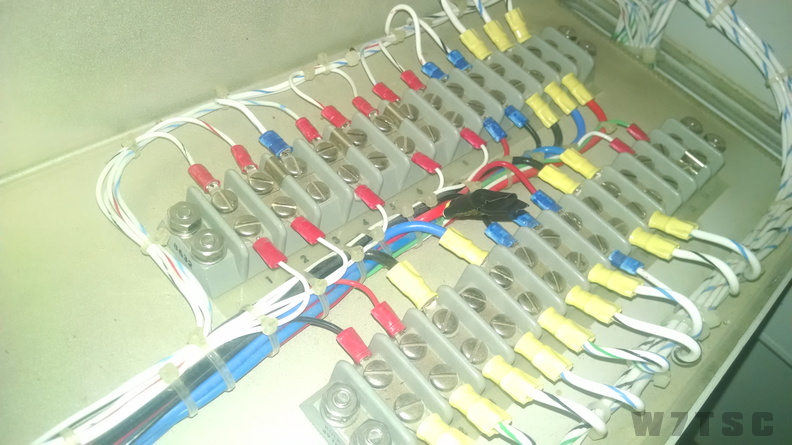
The following photo shows how the three wires were redistributed.
The last item I needed to address was the proper strapping of the PAs. Thanks to Jim Stitzinger (WA3CEX), Jim Jones (W0NKN), and especially Bill Carns (N7OTQ) I was able to discover the power supply could be easily strapped for 240V. In this case, I was able to move one wire in the Power Distribution panel and swap strapping in the plug.
For 240V single-phase, the PA uses the first and third power inputs at the power plug. This meant the PA was already partially wired the way I needed. BUS A needed no change. However, I was only using A and B BUS; the second AC input had to be where the BUS C input was. Therefore, I had to disconnect the C input and replace it with B.
I didn’t relish making this change in the multi-wire plug even though I would have to make the change in strapping there anyhow. My goal was to move as few wires as possible. Instead of re-wiring the plugs at each PA, I made the change by moving the BUS B wire to the BUS C lug on the Terminal Block in the Power Distribution Panel. See the following table and Figure 6. This made the job much easier.
| Terminal | Old Signal | New Signal | Change |
| TB2-p3 | BUS A | 240V Hot A | No Change |
| TB2-p4 | BUS B | Not used in 240V config | Moved to TB2-p5 |
| TB2-p5 | BUS C | 240V Hot B | Removed and taped over for safety (comes from PA breaker; no Phase C power present) |
Strapping the PA Power Supply
With power distribution now set up to properly provide 120 where needed and 240 to the PAs, it was time to turn my attention to the PAs. The following chart shows the incoming power to the HF-8032 PA Power Supply:
| Power Amp Power plug pin | Signal | Three - Phase Configuration | Single Phase Configuration |
| 1 | Phase A | Goes to TB2 #3 | No Change at plug |
| 7 | Phase B | Goes to TB2 #4 | No Change at plug; Phase B Feed side of TB2 #4 moved to TB2 #5 : TB2 #4 feed side left open; nothing feeds to J1 p7 at the Power Amp in Single Phase |
| 10 | Phase C | Goes to TB2 #5 | No Change at plug; Phase C Feed side of TB2 #5 removed, taped over : TB2 #4 Phase B feed wire moved to TB2 #5; Phase B now goes to J1 p10 at the Power Amp |
| 15 | Ground | Ground | No Change at plug |
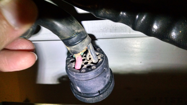
The only thing left was to properly strap the incoming plug so the PA knew it was operating on 240VAC. When I finally pulled out one of the two PA Power Supplies, I found a strapping diagram on the back that agreed with the information I had been provided earlier.
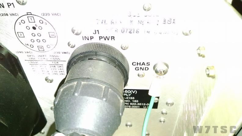
The strapping needed for 240VAC required moving the strap from pin 2, to pin 14 as listed in this table:
| Power Amp Power plug pin | Signal | 240V Single-phase config |
| 2 | 208V | No connect |
| 3 | 220V | No connect |
| 5 | Common (GND) | Connect to pin14 |
| 14 | 240V | Connect to pin 5 |
| 16 | 230V |
No connect |
|
J1 strapped for 208 VAC, pin 5 to pin 2 |
Back side of J1, note strapping jumper |
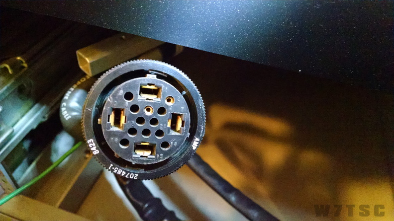
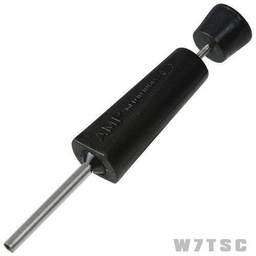
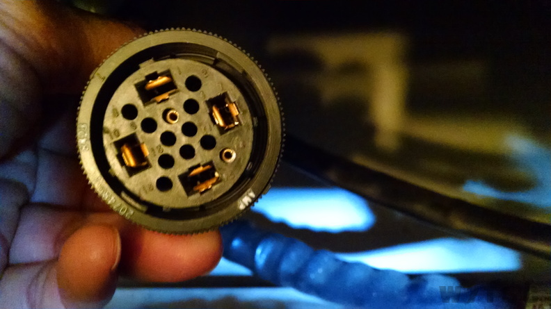
Using an Amp 305183 terminal extraction tool, I removed the jumper from pin 2 and relocated it to pin 14. See figure 9 for what the extraction tool looks like, and figure 10 for the completed re-strapped plug. This was done for both PA Power Supplies.
 |
J1 strapped for 240, pin 5 to pin 14 |
Power-Up
With all the changes made, wiring diagrams double-checked and all circuit breakers OFF inside the van, I then applied power at the Service Disconnect. Checking the voltmeter on the Power Distribution Panel, I found 120 on Phase A and Phase B, and nothing on Phase C (which had been disconnected). I should note here that due to how the Frequency Meter is wired, it relies on Phase C, but if a change is made to put Phase B on it to “see” frequency on the meter, we also then show 110 on Phase C on the voltmeter. This for me was undesired, therefore I trusted the incoming frequency was at 60Hz from the power company. I did not want to introduce soldering to unhook some wires and attach others; this was beyond the intent of the changes, which is to allow quickly switching back to 3-phase operation if I ever so desire.
Once voltage was verified, I then switched on the Main breaker, which would apply power to the A and B BUS, and from there to the various other breakers and equipment via other smaller fuses. The shelter fans immediately came on with the Main breaker and sounded operational. Next I turned on the shelter lights and one set of outlets, then checked the AMP gauge. With no smoke, sparks or other problems noted, I began to switch on other equipment and continue to monitor.
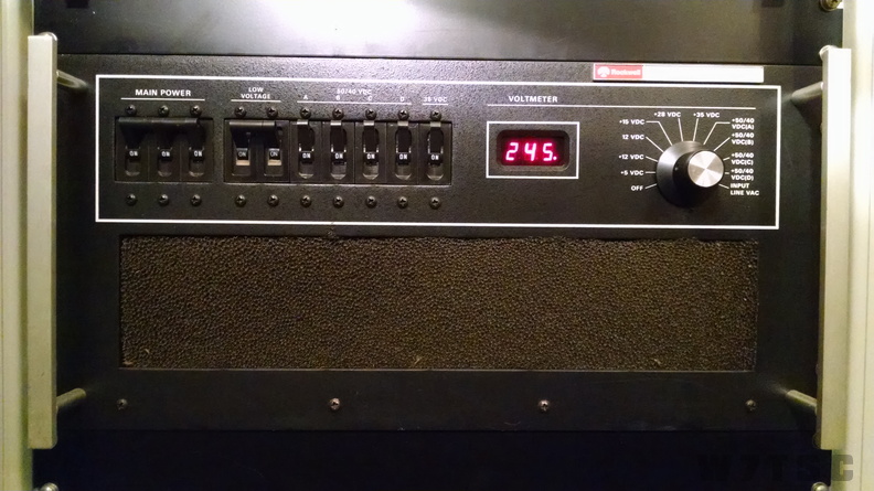
Once I got to the Receivers and Exciters, I then turned them on in their equipment rack and found they powered-up just fine. The radios operated on BUS A for one set and BUS B for another set; both were working. Turning on the PA Power Supply with the meter set to the incoming Input Line VAC, showed 245, which should be within the limits to properly operate.
At this point I was confident the change to single-phase power was successful and it would now allow me to turn on the facility and continue troubleshooting radio systems and working on other projects without worrying if the MEP-005 generator was going to go out on me again.
Having constant reliable power makes the hobby more fun.
Asa Jay Laughton
MSgt, USAFR, Retired
W7TSC – Grid DN17EP
Appendix A – Power Distribution Summary
| Circuit Breaker | Amp Rating | Description | Original Phases | Notes for Single-Phase |
| CB1 | 90 | Main | A,B,C | C not needed (unused) |
| CB2 | 40 | PWR AMP | A,B,C | C not needed (unused) |
| CB3 | 20 | RCVR/XCTRA,B | A,B | No Change |
| CB4 | 30 | ECU | A,B,C | C not needed (unused) |
| CB5 | 30 | Utility Outlets | A only | No Change |
| CB6 | 30 | Utility Outlets | B only | No Change |
| CB7 | 20 | Console | C only | Move to A |
| CB8 | 5 | Lights | B only | No Change |
| CB9 | 5 | ANT CPLR 1 | C only | Move to B |
| CB10 | 5 | ANT CPLR 2 | A only | No Change |
| Nomenclature | Description | Volts | Phases Used | Hertz | Max Watts | Units in Shelter |
| HF-8054A | Receiver | 115 +/-10% | 1 | 47 to 420 | 80 | 2 |
| HF-8014A | Transmitter | 115 +/-10% | 1 | 47 to 420 | 80 | 2 |
| HF-8064B | Bandpass Filter | 115 +/-10% | 1 | 47 to 420 | 50 | 2 |
| HF-8023 | Amplifier | 208/220/230/240 +/-10% | 3 | 47 to 63 or 380 to 420 | 3200 | 2 |
| HF-8032 | Power Supply | 208/220/230/240 +/-10% | 3 | 47 to 420 | with above | 2 |
| A29/A30 | Speech Plus | 12VDC | 12 | 2 | ||
| A22/A13 | TTY Modem | 12VDC | 12 | 2 | ||
| A31 | STU Power Supply | 120 | 1 | no TO listing | 1 | |
| A32/A33 | STU-5 | -48VDC | no TO listing | 2 | ||
| A23/A14 | VFTLG Modem | 12VDC | 12 | 2 | ||
| A21/A12 | Modem P/S | 115 | 1 | no TO listing | 2 | |
| 1A12 | Frequency Inverter | 208 -5+15% | 3 | 50, 60 or 400 | 6500 | 1 |
Appendix B – Summary of Changes for
Single-phase Operation
- Incoming Power Cable
| Wire Color | From | To |
| Red | Hot 1 | A |
| White | Hot 2 | B |
| Black | Ground | C |
| Green | Neutral | Neutral |
- Power Entry Panel
| Signal | From | To |
| A | No Change | No Change |
| B | No Change | No Change |
| C | Current Sense and Filter C | GND Lug |
| Neutral | No Change | No Change |
- Power Distribution
| Signal | From | To |
| Phase C Supply | BUS C – Hole 1 | Removed (taped) |
| Fuse F5-3A – Blower | BUS C – Hole 4 | BUS B – Hole 4 |
| CB7 – Console Lights | BUS C – Hole 5 | BUS B – Hole 5 |
| CB9 – Antenna Coupler 1 | BUS C – Hole 6 | BUS A – Hole 5 |
| PA Power Supply Phase C | BUS C – Hole 7 | Not Moved (unused) |
| ECU Phase C | BUS C – Hole 8 | Not Moved (unused) |
| PA Power Supply Phase B | TB2 – 4 | TB2 – 5 |
| PA Power Supply Phase C | TB2 – 5 | Disconnect (taped) |
- HF-8032 PA Power Supply
| Signal | From | To |
| 240 VAC Strapping | J1 – P2 | J1 – P14 |
Appendix C – Instructions on Returning to 208 VAC,
3-phase Power
- Incoming Power Cable
| Wire Color | From | To |
| Red | Hot 1 | A |
| White | Hot 2 | B |
| Black | Hot 3 | C |
| Green | Neutral | Neutral |
- Power Entry Panel
| Signal | From | To |
| A | No Change | No Change |
| B | No Change | No Change |
| C | GND Lug | Current Sense and Filter C |
| Neutral | No Change | No Change |
- Power Distribution
| Signal | From | To |
| Phase C Supply | Removed (taped) | BUS C – Hole 1 |
| Fuse F5-3A – Blower | BUS B – Hole 4 | BUS C – Hole 4 |
| CB7 – Console Lights | BUS B – Hole 5 | BUS C – Hole 5 |
| CB9 – Antenna Coupler 1 | BUS A – Hole 6 | BUS C – Hole 5 |
| PA Power Supply Phase C | BUS C – Hole 7 | As-Is |
| ECU Phase C | BUS C – Hole 8 | As-Is |
| PA Power Supply Phase B | TB2 – 5 | TB2 – 4 |
| PA Power Supply Phase C | Disconnect (taped) | TB2 – 5 |
- HF-8032 PA Power Supply
| Signal | From | To |
| 240 VAC Strapping | J1 – P14 | J1 – P2 |