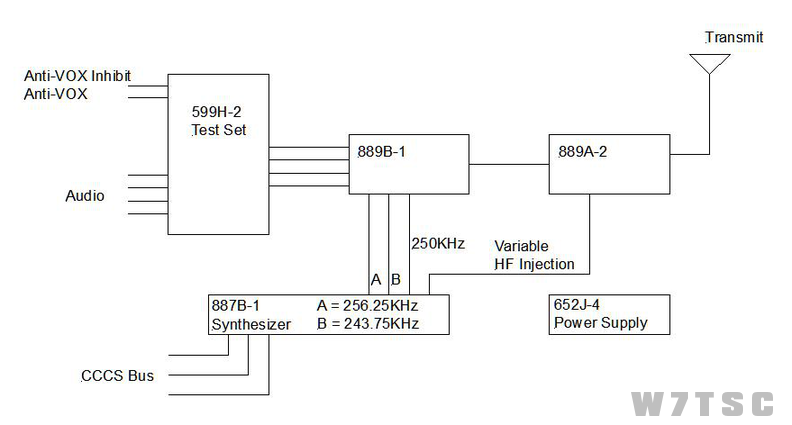
599H-2 - Test Set
Routes audio from OK-145 to IF Translator circuits for 1KHz CW, VOX and Anti-VOX Inhibit
The difference between the low level and high level self-test is that high level self-test has one more amplifier applied.
652J-4 - Power Supply
Provides all switched and continuous voltages to all other GRT-17 Slices
The continuous voltage oscillator section is enabled by 120VAC applied when that circuit breaker is placed in ON position.
The switched voltage oscillator section is enabled by a ground through the 1A31A6 Air Flow Interlock
47-460Hz is the frequency of the two oscillator sections (400Hz secondary oscillator output with 115VAC)
115VAC at 400Hz is NOT monitored by A1U1
887B-1 - Frequency Synthesizer (Same as Receiver)
Produces all frequencies necessary for mixing:
- 9.9MHz
- 9.9KHz
- 250KHz
- 256.25KHz
- 243.75KHz
- Variable injection
9.9KHz Phase-Lock-Loop (ØLL) outputs 107.1500 - 79.1501MHz to RF Translator
10KHz ØLL outputs 93.29 - 64.31MHz to 9.9KHz ØLL
9.9MHz ØLL provides outputs of 9.9MHz to 9.9KHz ØLL, A20 x10 multiplier, 6.29KHz multiplex divider, and a 100KHz reference to the 250KHz ØLL
250KHz ØLL provides 250KHz reference to 6.29KHz multiplex ØLL and 250KHz to 889B-1 for demodulation
6.29KHz multiplex ØLL provides 243.710KHz and 256.29KHz to the 889A-2 for demodulation
888B-1 - IF to RF Translator
Contains the RF translator (No Preselector) and converts IF to RF
- Converts 250KHz +/- 6.29KHz to window frequency
889A-7 - IF Translator
Converts Audio to IF (250KHz +/- 6.29KHz
Receiver slices 887B-1 and 652J-4 can be interchanged with the same Transmitter slices.
- Main Breaker applies power to the rack
- RCV Breaker applies power to the 652J-4 to turn on continuous voltages (Blower Breaker must also be ON)
- Enable Receiver at OK-145 Control head
- When positive air pressure is felt (from the blower) interlock 1A31A6 closes providing ground to Control switched voltages in the 652J-4.
- Voltages are then routed to individual areas
System will NOT Tune Complete until the PA does.