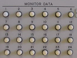
The Power Amplifier in the AN/TSC-60(V)2 and (V)4 go through seven specific tune steps. All conditions for each step must be met before the PA moves on to the next step.
The Maintenance Display panel located above the center station OK-145 computer control head, has a Monitor Data display consisting of 24 independent lamps. When the monitor is switched to the PA, the primary lamps to be concerned with are numbered 22, 23 and 24. These indicate the tune steps as they progress.
NOTE: The light sequence is NOT a Binary numerical sequence.
The following list illustrates the lamps during the Tune Steps, a 1 indicates the lamp is lit, a zero means it is extinguished:
- 100
- 110
- 010
- 011
- 001
- 101
- 111

1: Ready to Tune
- Maintenance Display lamps 22, 23, 24 = 100
- Must have power applied
- Vents must be open
- Control ON
- Filament ON
- Plate ON (after 30 seconds)
- 600 ohm or less DC to ground, antenna continuity
- RF applied, but not used
2: Coarse Tune
- Lamps = 110
- RF applied, but not used
- DC continuity
- Key command applied
- All servos driven to coarse position
3: Fine Tune 1
- Lamps 010
- All servos stopped
- Amp Driver and PA tube current enabled
- TGC enabled at 0 to -10VDC
- Loading servo disabled
- Load resistors placed on output
4: Fine Tune 2
- Lamps 011
- Loading servo enabled
- All servos must Null
- Must generate RF Prove Command
- RF in excess of 100 watts
- If a coupler is enabled, it must show Tune Complete
5: Fine Tune 3
- Lamps 001
- Same steps as 4
6: Full Power Trim
- Lamps 101
- Tune resistors removed
- TGC reverts to ALC
- Tubes go to 2.8Kw
- Operate Request
7: Operate
- Lamps 111
